In the Video
Japanese【日本語】
English【英語】
1. Overview
We will understand the “L blinking” that is the first step to start electronic work. Learn the basics with a program that controls LEDs.
We will learn using Arduino and ESP32.
2. Overall flow of Smart Remote Controller Production
Regarding the contents of the L blinking, this post is complete.
However, this time it will be a series in which we will eventually create a smart remote control, and we will distribute it in a total of 7 posts.
This time it will be the second LED electronic work.
| No | Item | Content | Hard | Soft | Note |
|---|---|---|---|---|---|
| 1 | Overall flow, system configuration, items used, reasons for selection, development environment, etc. | – | – | Another Post | |
| 2 | Green LED | Learn the basics for beginners. We will make “L blinking” that lights up and blinks the LED. | 〇 | 〇 | This Post |
| 3 | Infrared receiving sensor | Description of infrared receiving sensor Schematic to Wiring, Software | 〇 | 〇 | Another Post |
| 4 | Infrared transmission LED | Infrared transmission LED description Schematic to Wiring, Software | 〇 | 〇 | |
| 5 | LED operation with smartphone(at home) | We will create software to operate the LED with smartphone. (Web server function, SPIFFS operation) | – | 〇 | |
| 6 | Remote control with smartphone(at home) | We will create software that to operate the remote control with smartphone indoors. (Button name, signal save/read) | – | 〇 | |
| 7 | Operate from outside And AI speaker cooperation | We will create software to operate the remote control with smartphone from the outdoors, and AI speaker cooperation. | – | 〇 |
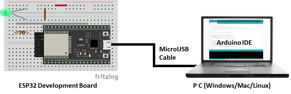
3. The development environment
Arduino was developed in Italy under the philosophy of “making things easier and easier to understand”.
Currently, it is widely used for learning all over the world, and the library is also substantial.
So, if you want to start electronic work, I think this is the only development environment.
Therefore, I use Arduino at this time.
4. Schematic and resistance calculation
The wiring is done to light the LED, but the power supply is the operating voltage of the ESP32, which is 3.3V, and the forward voltage of the LED is 2V. So a direct connection would overload it and destroy the LED.
Therefore, the resistors are wired in series. Regarding the value of the resistor, the voltage applied is constant from the LED specification, so the voltage across the resistor is 3.3V from the power supply minus the LED voltage of 2V, which is 1.3 volts.
Since the current is connected in series, the LED and the resistor both flow in the same way.
So, 1.3 volts divided by 20 mA equals 65 ohms.
This time, 65Ω was too bright, so I lowered it to 200Ω to reduce the current flow.
I don’t think it’s a problem to use resistors larger than the calculated values.
Note that reducing the resistance will destroy the LED.

5. Wiring diagram
we will perform wiring according to this circuit diagram.
Here is the wiring diagram.

6. Software
Here is the Arduino sketch(program). I created this from a sample of ArduinoIDE.
/*
  Blink

  Turns an LED on for one second, then off for one second, repeatedly.

  Most Arduinos have an on-board LED you can control. On the UNO, MEGA and ZERO
  it is attached to digital pin 13, on MKR1000 on pin 6. LED_BUILTIN is set to
  the correct LED pin independent of which board is used.
  If you want to know what pin the on-board LED is connected to on your Arduino
  model, check the Technical Specs of your board at:
  https://www.arduino.cc/en/Main/Products

  modified 8 May 2014
  by Scott Fitzgerald
  modified 2 Sep 2016
  by Arturo Guadalupi
  modified 8 Sep 2016
  by Colby Newman

  This example code is in the public domain.

  https://www.arduino.cc/en/Tutorial/BuiltInExamples/Blink
*/

const byte LED_PIN  = 22;  // green LED

// the setup function runs once when you press reset or power the board
void setup() {
  Serial.begin(115200);
  // initialize digital pin LED_BUILTIN as an output.
  pinMode(LED_PIN, OUTPUT);
}

// the loop function runs over and over again forever
void loop() {
  digitalWrite(LED_PIN, HIGH);   // turn the LED on (HIGH is the voltage level)
  Serial.println ( "led on" );
  delay(1000);                       // wait for a second
  digitalWrite(LED_PIN, LOW);    // turn the LED off by making the voltage LOW
  Serial.println ( "led off" );
  delay(1000);                       // wait for a second
}

Comments