In the Video
Japanese【日本語】
English【英語】
1. Overview
I would like to work electronically on the infrared transmission LED.
We will understand the mechanism of remote control signals and modulation, and create circuits using LEDs and transistors.
This electronic work will eventually become a series of making a smart remote controller.
2. Overall flow of Smart Remote Controller Production
We will eventually create a smart remote control, and we will distribute it in a total of 7 posts.
This is the fourth infrared transmission LED.
| No | Item | Content | Hard | Soft | Note |
|---|---|---|---|---|---|
| 1 | Overall flow, system configuration, items used, reasons for selection, development environment, etc. | – | – | Another Post | |
| 2 | Green LED | Learn the basics for beginners. We will make “L blinking” that lights up and blinks the LED. | 〇 | 〇 | |
| 3 | Infrared receiving sensor | Description of infrared receiving sensor Schematic to Wiring, Software | 〇 | 〇 | |
| 4 | Infrared transmission LED | Infrared transmission LED description Schematic to Wiring, Software | 〇 | 〇 | This Post |
| 5 | LED operation with smartphone(at home) | We will create software to operate the LED with smartphone. (Web server function, SPIFFS operation) | – | 〇 | Another Post |
| 6 | Remote control with smartphone(at home) | We will create software that to operate the remote control with smartphone indoors. (Button name, signal save/read) | – | 〇 | |
| 7 | Operate from outside And AI speaker cooperation | We will create software to operate the remote control with smartphone from the outdoors, and AI speaker cooperation. | – | 〇 |
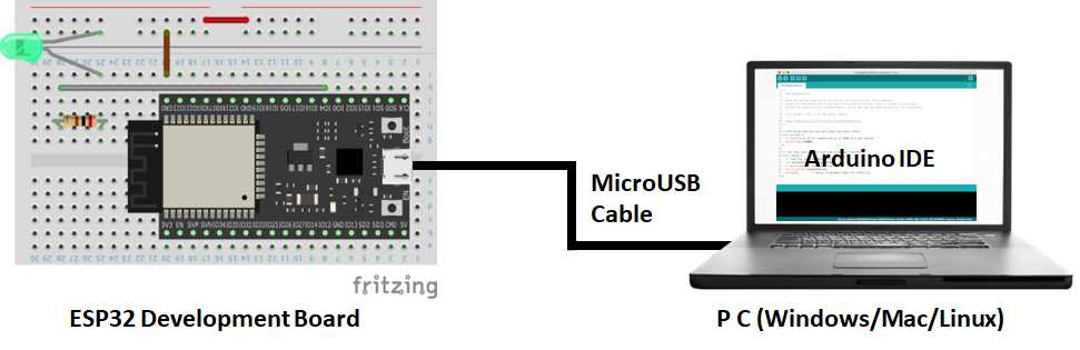
3. The development environment
Arduino was developed in Italy under the philosophy of “making things easier and easier to understand”.
Currently, it is widely used for learning all over the world, and the library is also substantial.
So, if you want to start electronic work, I think this is the only development environment.
Therefore, I use Arduino at this time.
5. Circuit diagram
When IO32 of ESP32 is set to output and this terminal is turned ON, a large current flows between the collector and the emitter by passing a current through the base of the transistor, and the infrared transmission LED can be lit.

6. Wiring diagram
we will perform wiring according to this circuit diagram.
Here is the wiring diagram.

6. Software
Here is the Arduino sketch(program).
//*************************************************************************
//  Ir Send Ver2023.1.22
//  Arduino board : ESP32(Arduino core for the ESP32) by Espressif Systems ver 2.0.6
//  Written by IT-Taro
//***********************************************************************

const byte IR_S_PIN = 32;       // Transmission control with GPIO32
// Set transmission data
unsigned short irData[] = { 303,171,47,41,46,41,46,128,46,128,46,41,47,127,47,41,46,41,46,41,46,128,46,41,46,41,46,128,46,41,46,128,46,41,47,127,47,41,46,41,46,128,46,41,46,41,46,41,44,43,44,130,46,128,47,127,47,128,44,43,44,130,46,41,44,43,44,43,44,130,45,130,46,41,46,41,44,130,44,43,44,43,44 };  // ### [Data rewrite required] ###

// Initial settings at startup
void setup() {
  Serial.begin(115200);
  Serial.println();
  pinMode(IR_S_PIN, OUTPUT);

  // Execute function to transmit infrared
  irSend ();
  Serial.println("SndOK");
}

void loop() {

}

// Infrared transmission processing
void irSend () {
  // Local variable definition
  unsigned short irCount = 0; // Number of HIGH and LOW signals
  unsigned long l_now = 0;    // Hold transmission start time
  unsigned long sndt = 0;     // Elapsed time from transmission start
  // Calculate the number of HIGH and LOW signals
  irCount = sizeof(irData) / sizeof(irData[0]);
  // Acquire transmission start time
  l_now = micros();
  // Loop for the number of signals 0 and 1 with a For statement
  for (int i = 0; i < irCount; i++) {
    // Calculate signal end time from transmission start
    sndt += irData[i];
    do {
      // If "i" is an even number, the infrared is ON, if it is an odd number, it remains OFF.
      // Transmitting with ON time at carrier frequency 38kHz (approximately half of 26μSec cycle)
      digitalWrite(IR_S_PIN, !(i&1));
      microWait(13);
      // Transmit at carrier frequency 38 kHz (approximately half of 26 μSec cycle) during OFF time
      digitalWrite(IR_S_PIN, 0);
      microWait(13);
    // Loop from transmission start to signal end time
    } while (long(l_now + (sndt * 10) - micros()) > 0);
  }
}

// Wait in microseconds
void microWait(signed long waitTime) {
  unsigned long waitStartMicros = micros();
  // Loop processing (wait) with While until the specified microseconds have passed
  while (micros() - waitStartMicros < waitTime) {};
}

Comments