
In the Video
Japanese【日本語】
English【英語】
1. Overview
I would like to work electronically on the infrared receiving sensor.
We will implement the mechanism and usage of the infrared reception sensor, acquisition of remote control signals, etc.
This electronic work will eventually become a series of making a smart remote controller.
2. Overall flow of Smart Remote Controller Production
We will eventually create a smart remote control, and we will distribute it in a total of 7 posts.
This time it will be the third Ir receive electronic work.
| No | Item | Content | Hard | Soft | Note |
|---|---|---|---|---|---|
| 1 | Overall flow, system configuration, items used, reasons for selection, development environment, etc. | – | – | Another Post | |
| 2 | Green LED | Learn the basics for beginners. We will make “L blinking” that lights up and blinks the LED. | 〇 | 〇 | |
| 3 | Infrared receiving sensor | Description of infrared receiving sensor Schematic to Wiring, Software | 〇 | 〇 | This Post |
| 4 | Infrared transmission LED | Infrared transmission LED description Schematic to Wiring, Software | 〇 | 〇 | Another Post |
| 5 | LED operation with smartphone(at home) | We will create software to operate the LED with smartphone. (Web server function, SPIFFS operation) | – | 〇 | |
| 6 | Remote control with smartphone(at home) | We will create software that to operate the remote control with smartphone indoors. (Button name, signal save/read) | – | 〇 | |
| 7 | Operate from outside And AI speaker cooperation | We will create software to operate the remote control with smartphone from the outdoors, and AI speaker cooperation. | – | 〇 |
3. The development environment
Arduino was developed in Italy under the philosophy of “making things easier and easier to understand”.
Currently, it is widely used for learning all over the world, and the library is also substantial.
So, if you want to start electronic work, I think this is the only development environment.
Therefore, I use Arduino at this time.
4. Mechanism of Infrared Receiving Sensor
First, although infrared rays are invisible to the human eye, they are a type of electromagnetic wave, just like light.
When this sensor receives an infrared ray, the Vout terminal becomes LOW, that is, ground.
HIGH is output when there is no signal.
It seems to be HIGH when there is a signal and LOW when there is no signal, but this is how it works.
Since the ESP32 3.3V terminal and ground terminal are connected to the VCC and ground terminals of the sensor, when the sensor is HIGH, the voltage 3.3V input to VCC is output from Vout.

5. Circuit diagram
The sensor has three terminals, and the two terminals of VCC and ground are power supplies for operation.
The VCC terminal connects the 3.3V of the ESP32, and the ground terminal connects with the ground of the ESP32.

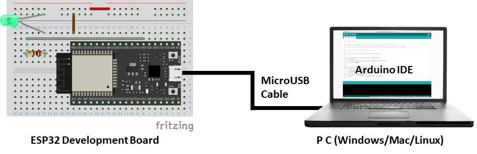
6. Wiring diagram
we will perform wiring according to this circuit diagram.
Here is the wiring diagram.

6. Software
Here is the Arduino sketch(program).
//*************************************************************************
//  Ir Receive Ver2023.1.20
//  Arduino board : ESP32(Arduino core for the ESP32) by Espressif Systems ver 2.0.6
//  Written by IT-Taro
//***********************************************************************

const byte IR_R_PIN = 23;     // Remote control reception with GPI23

// Initial settings at startup
void setup() {
  Serial.begin(115200);
  Serial.println();
  Serial.println("IrRecvStart");
  pinMode(IR_R_PIN, INPUT);
}
// Repeat infrared reception process
void loop() {
  if ( irRecv () ) {          // Execute infrared reception processing
    Serial.println();
    Serial.println("RcvOK");  // Displayed when the signal is received normally
  } else {
    Serial.println();
    Serial.println("NoSig");  // Displayed when there is no signal for 30 seconds
  }
}

// Infrared reception (signal reception or processing for 15 seconds))
bool irRecv () {
  // Define variables (local variables) used in the irRecv function
  unsigned short irCount = 0;   // Number of HIGH and LOW signals
  unsigned long lastt = 0;      // Hold previous elapsed time
  unsigned long deltt = 0;      // Difference time from previous one
  unsigned long sMilli;         // Start time of this process
  unsigned long sMicro;         // Processing start time
  unsigned long wMicro;         // wait start time
  bool rState = 1;              // Infrared receiver module status 0: LOW, 1: HIGH
  sMilli = millis();            // Get the current system time (get in milliseconds)
  // Infinite loop until specific condition (signal received or 15 seconds elapsed)
  while(1) {
    // Get start time to wait for Ir reception
    wMicro = micros();          // Get current system time (get in microseconds)
    // Waiting for reception of inverted signal
    while (digitalRead(IR_R_PIN) == rState) {
      // When 0.5 seconds or more have passed after starting to wait
      if (micros() - wMicro > 500000) {
        // After waiting for 0.5 seconds or more
        if ( irCount > 10 ) {
          return true;    // Successfully completed
        }
        // If there are not more than 10 0,1 signals, receive again from zero due to noise
        irCount = 0;
        delay(1); // For watchdog timer (must be reset within 3 seconds)
      }
      // After 15 seconds or more of processing, T.O.
      if ( millis() - sMilli > 15000 ) {
        return false;    // Ends after 15 seconds (no reception)
      }
    }
    // Get the current time and elapsed time at the start of signal reception
    if ( irCount == 0 ) {
      sMicro = micros();
      lastt = 0;
      irCount++;
      Serial.println("ir:");
    // Processing after starting signal reception processing (irCount is 1 or more)
    } else {
      // Calculate the elapsed time from the time when the status change of the infrared receiver last changed
      deltt = ( (micros() - sMicro)/ 10 ) - lastt;
      // Save the last changed elapsed time for the next elapsed time calculation
      lastt = lastt + deltt;
      irCount++;
      Serial.print(deltt);
      Serial.print(",");
    }
    // Change the value to detect state change in While next time
    rState = !rState;
  }
}

Comments